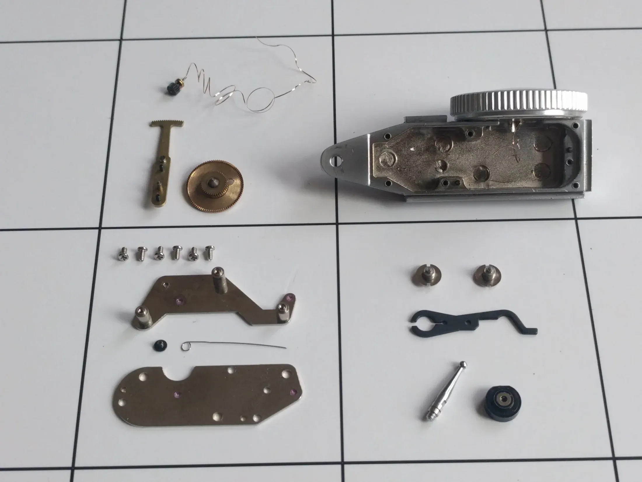
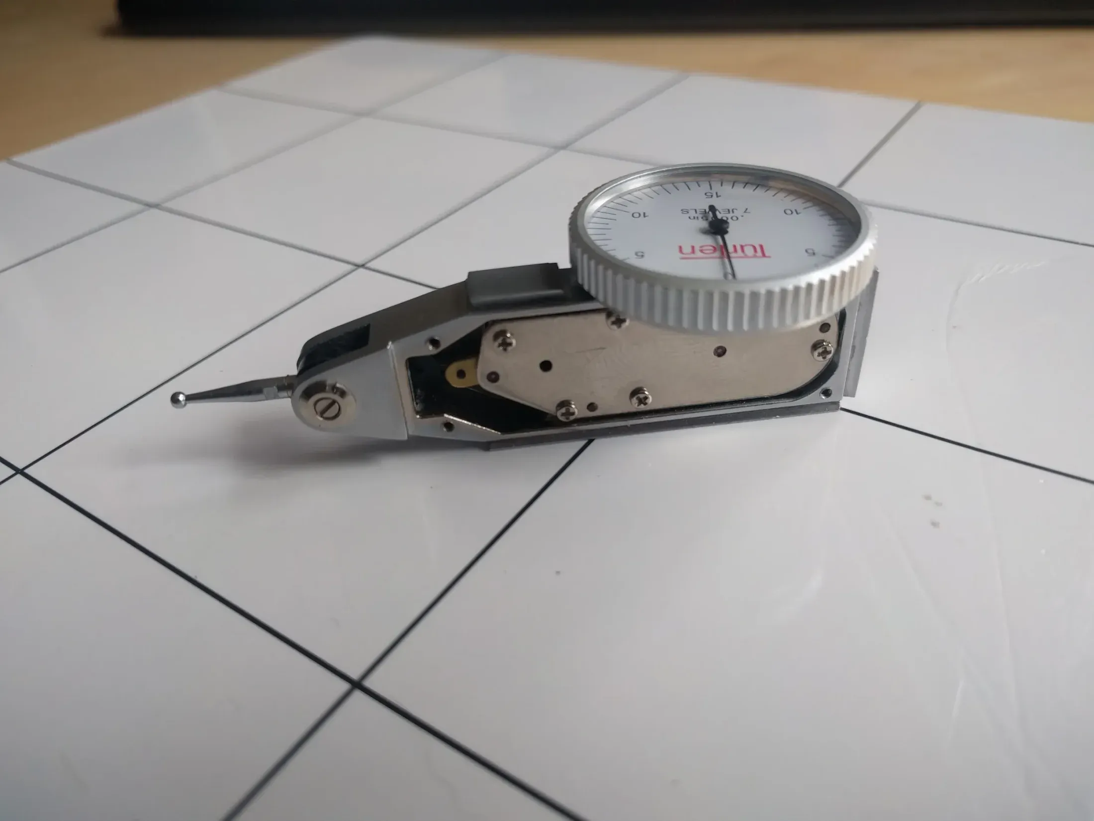
We use Test Indicators all the time at Other Machine Co; whether it’s during incoming part inspection or during final QA, they get a lot of use. Unfortunately, we recently had a casualty, and I was able to bring it home and tear it down. This is an inexpensive 5 tenths indicator from Amazon, by Türlen (available here). I’m not exactly sure how it was broken, but I was happy to take it apart.
I relied heavily on my iFixit Driver Kit and Magnetic Project Mat for this teardown. I highly recommend the former to all hardware folks - the array of drivers included in the set is expansive, considering the price, and the flexible driver extension is particularly handy. The magnetic project mat isn’t quite as useful as often, but I’d definitely recommend it to folks that deal with tiny fasteners regularly.
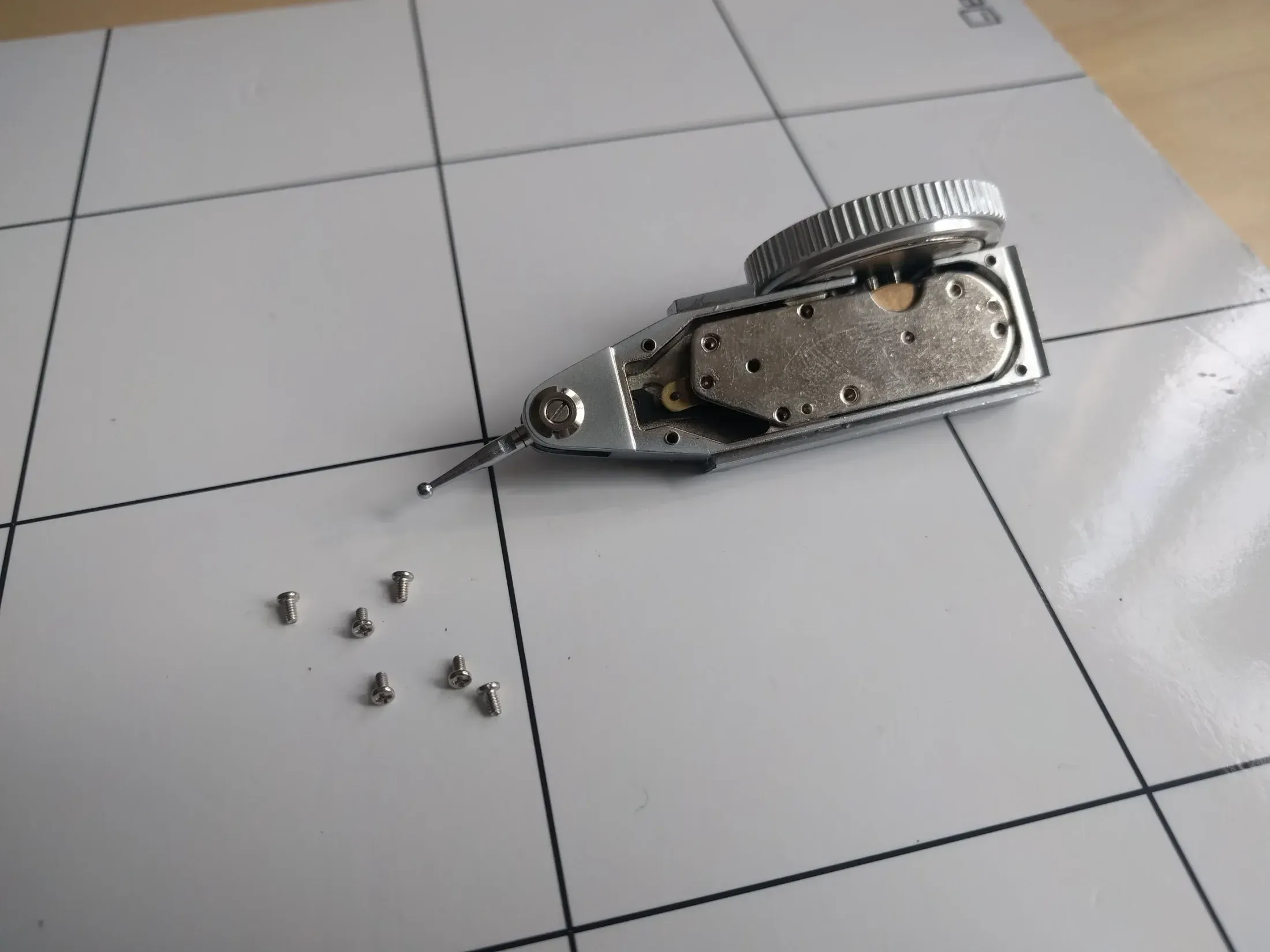
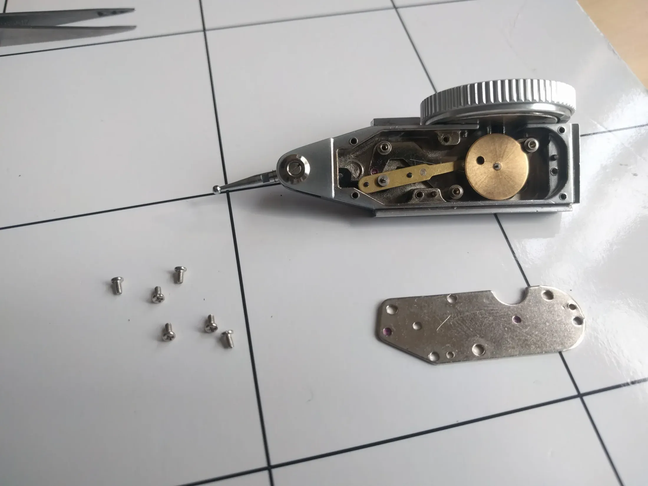
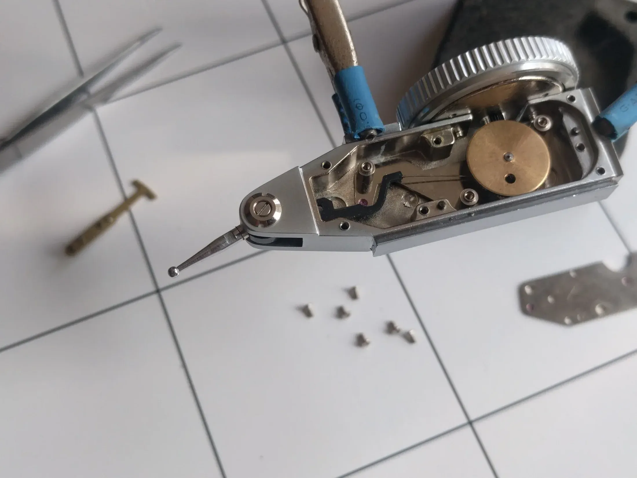
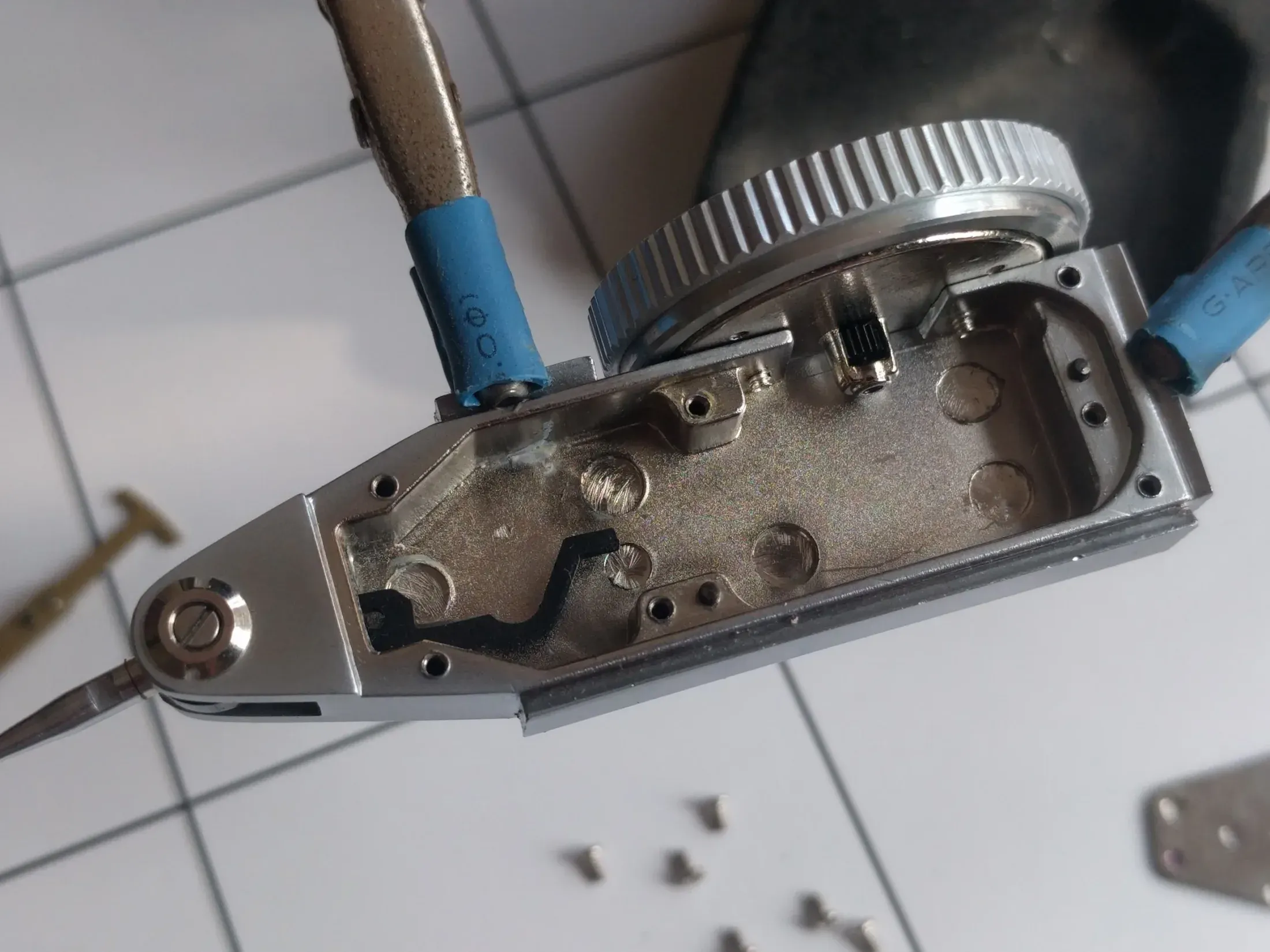
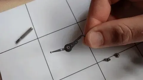
As seen above, the teardown started simply, with the removal of a few phillips screws. Although the lever action between the pivot assembly and the rest of the components was clearly broken, it was neat to see how these precision indicators really function. Once inside, I first removed the sector gear arm, and then proceeded to remove the rest of the parts, which came out easily.
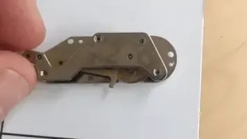
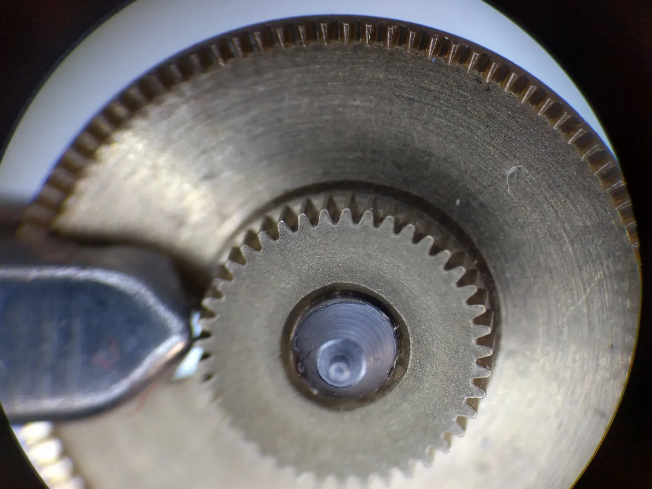
After removing as many of the internal parts as I could, I reassembled the sector gear arm and main gear between the two plates. Both the main gear and sector gear arm pivot on ruby bearings, which are pressed into the plates. You can see the tiny amount of pressure from my finger required to rotate the main gear here:
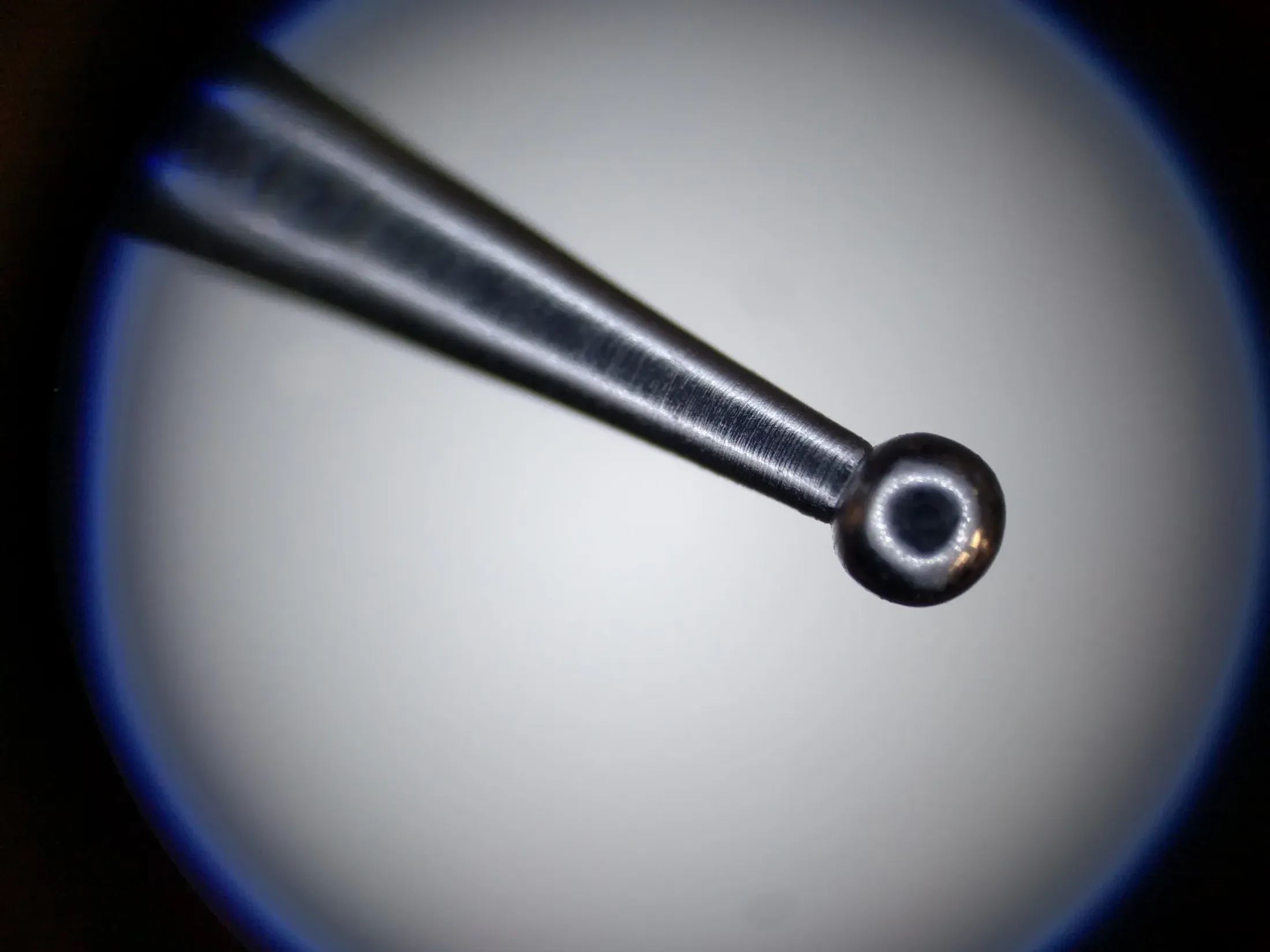
Next, I disassembled and examined the pivot assembly, which includes a long lever arm and the stylus subassembly.
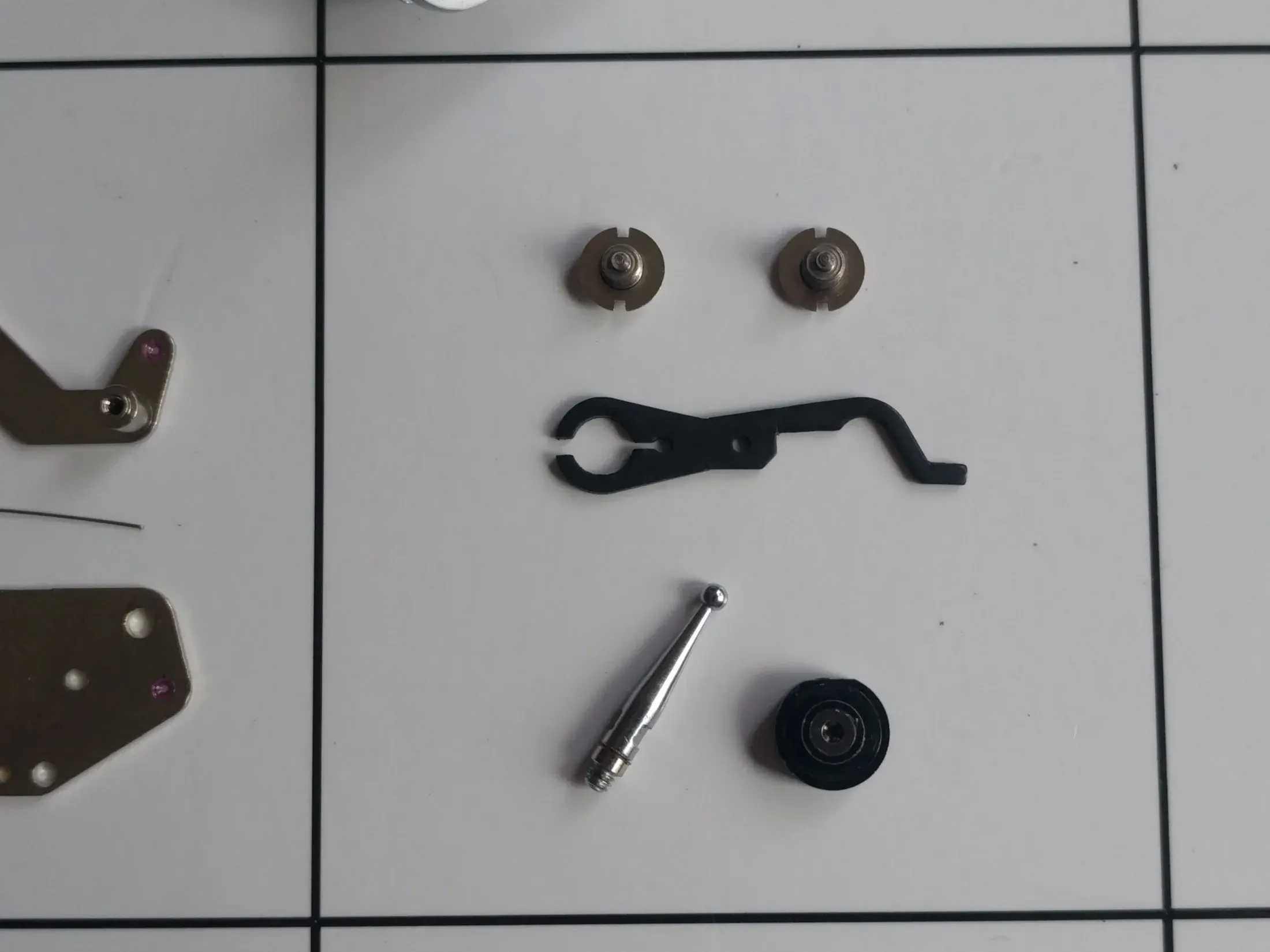
A retaining clip is built into the lever arm, as seen above, which captures the pivot assembly and allows the user to rotate the stylus freely during use.
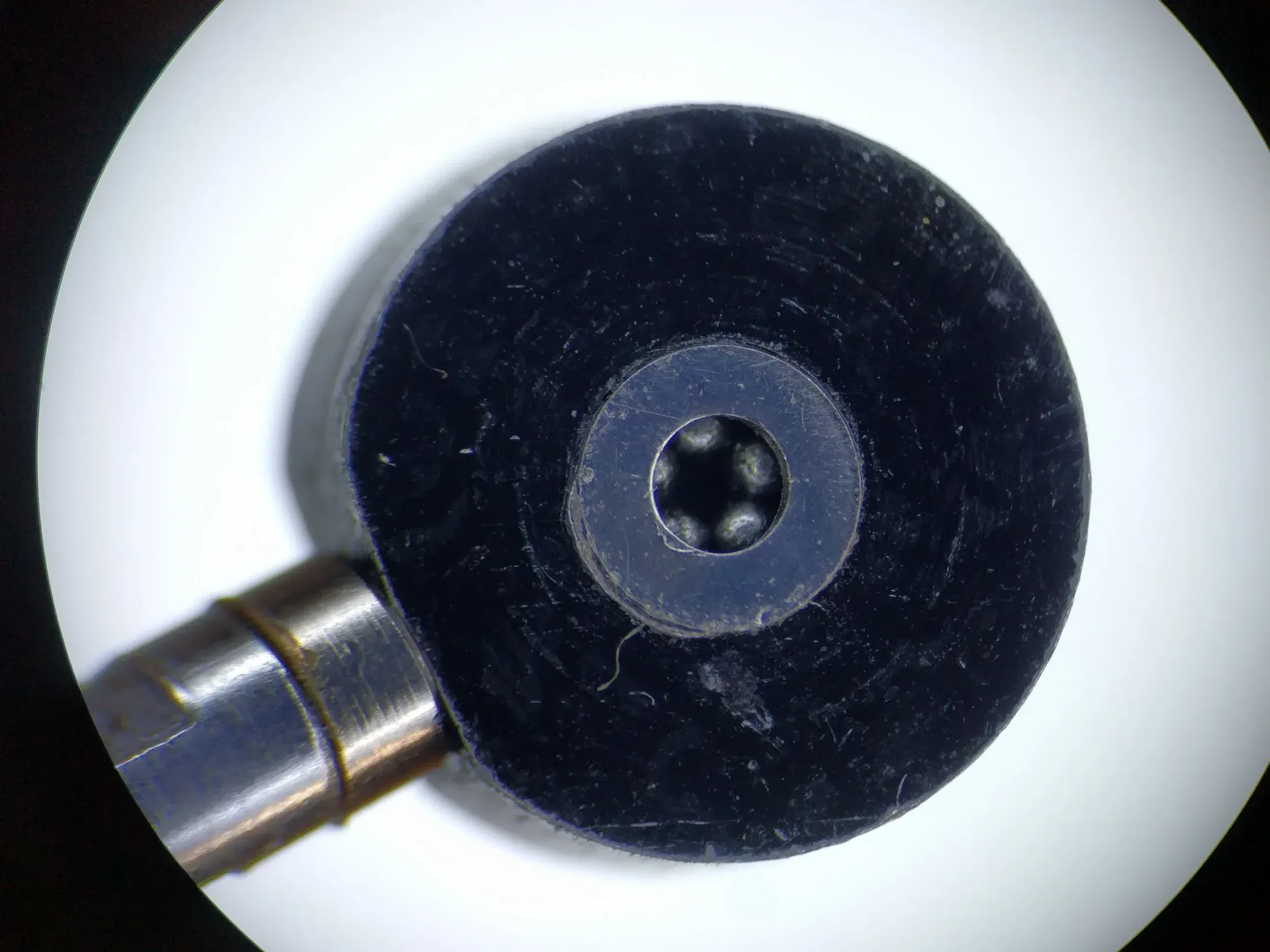
I was surprised to find a few bearing balls inside the main pivot component - this part holds the stylus and rides on two pointed screws, which gently secure it from either side.
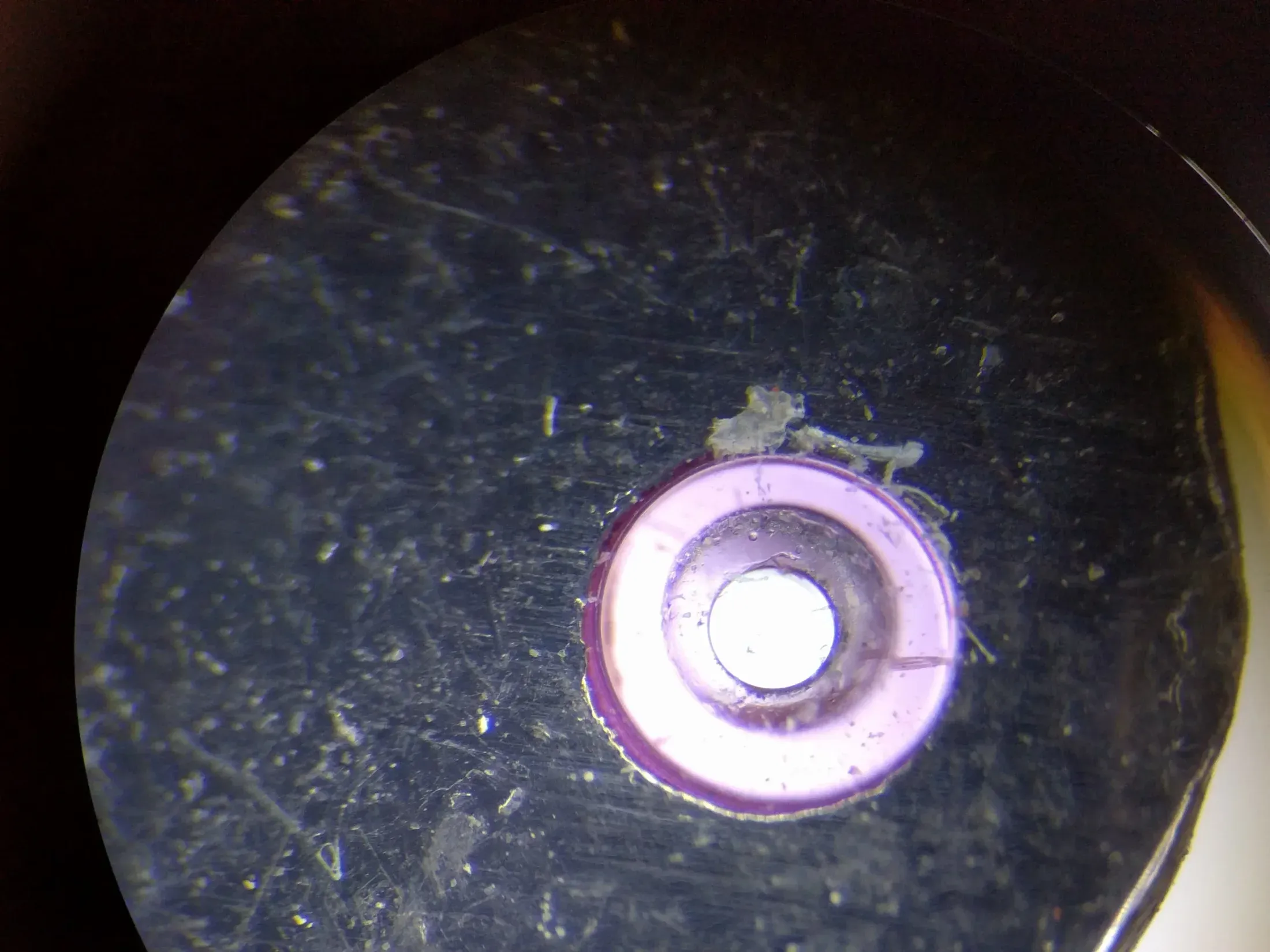
I was able to use our microscope to get some up-close shots of a few components. I took these photos with my phone, freehand, so I apologize for the quality.
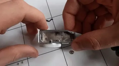
This final GIF explains the mess of wire that’s shown in the first photo of this post - it acts as a radial spring inside the indicator subassembly. Unfortunately, I was not able to remove the bezel to get a good look at the internals of this subassembly, but I was pretty satisfied with what I’d learned at this point.
I was impressed by the quality of the components in this indicator, considering the price. It’s definitely a good bargain! I always learn so much from doing teardowns, and this was no exception. The precision work in the gears was particularly surprising, but I suppose that without said precision, this would not be a five tenths indicator.
I hope you enjoyed this inaugural teardown on my blog. I’m hoping this is one of many.