A key contribution to precision machine tools was the understanding of the importance of flatness, and the development of processes that are used to make surfaces very flat. Henry Maudslay invented the first machine that could cut standard screw threads and contributed to the invention of the now-common surface plate, which serves an important role in metrology today. A classic book called Foundations of Mechanical Accuracy described this and other concepts in detail. It’s available as a PDF here and in print here.
Typically made of granite, surface plates act as a datum, or the basis upon which precise measurements and movements can be made. They can be finished to a variety of grades of flatness, based on their intended use, and can even be used to build up precise structures (that whole video is a must-watch, btw). When dealing with such flat surfaces, tiny imperfections or gradual wear can have drastic effects: using a gauge over the same spot on a surface plate, or leaving it in a space where the temperature varies by more than a few degrees, can negatively affect their flatness. Due to this, calibrating and conditioning your plate is important. The process is really neat, partially because it requires an autocollimator and an incredibly precise repeat-o-meter. Watch a great video from Tom Lipton about the process here.
The neat thing about surface plates is that they do not require precision tools to create. By using the “three plate method”, developed by Joseph Whitworth, flat surfaces can be created by using gravity and a simple hand-scraping tool, or by lapping the plates against each other. By starting with three plates of relative flatness, rubbing the plates against each other in alternating pairs to remove the high spots can yield fantastic results.
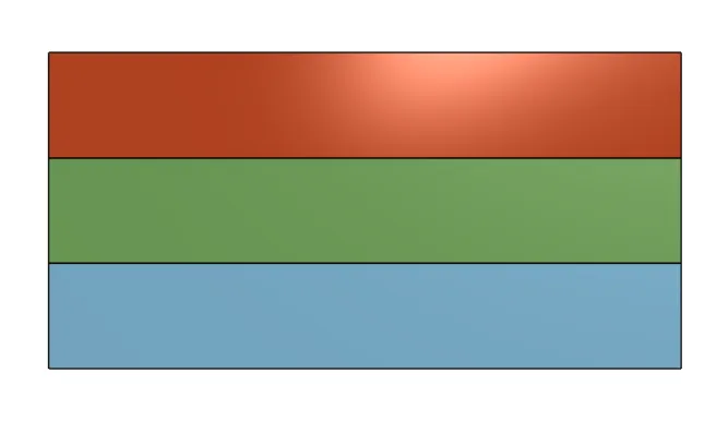
The process can be completed in six steps, and then repeated until the desired level of flatness is achieved. In this visual explanation, the surface finishes of the three plates are exaggerated. Before beginning this process, the three plates (Red, Green and Blue) should be machined or ground to as flat a surface as possible, to remove all unnecessary lapping work. In addition, a fine abrasive compound is often used between plates to assist in material removal. Tom also has a great video series about this, which includes some compound and technique recommendations.
Step 1
To begin, the Red and Green plates are lapped against each other in an alternating manner. That is, one plate remains stationary while the other is lapped against it, and then the opposite is performed:
At the completion of this step, the Red and Green plates “agree with” each other, but that is all.
Step 2
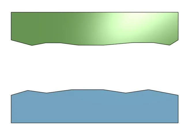
Next, the Red plate acts as the control (it remains stationary) while the Blue plate is lapped against it:
At the end of this step, both the Green and Blue plates have picked up the error from the Red plate. They do not agree with each other, however.
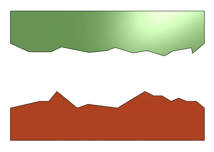
Step 3
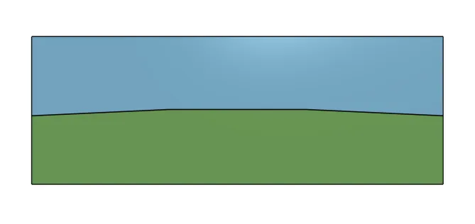
Next, the Green and Blue plates are lapped against each other in an alternating manner:
Since both of these plates picked up the error of the Red plate from the first two steps, lapping them together removes some of the error from the Red plate, bringing them closer to flat. At this point, the Green and Blue plates are more flat than the Red plate:
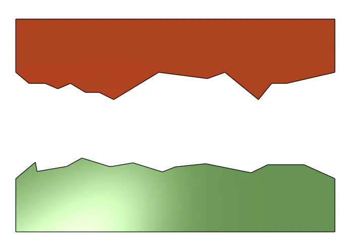
Step 4
Next, the Green plate acts as the control and the Red plate is lapped against it:
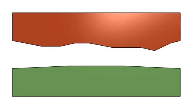
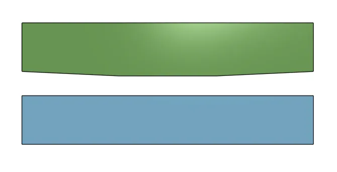
At the completion of this step, all three plates are of roughly equal flatness, but one (Green) is convex and the other two are concave:
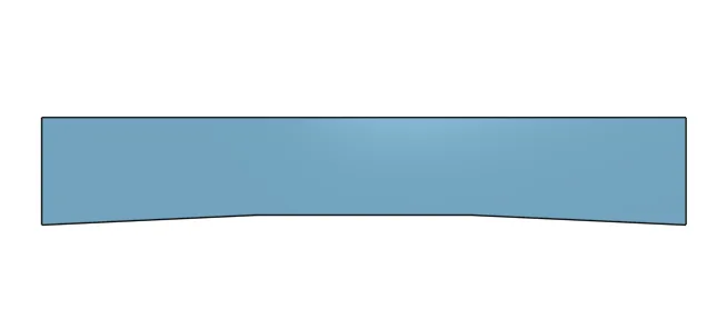
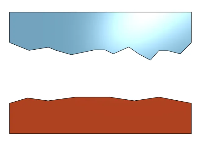
Step 5
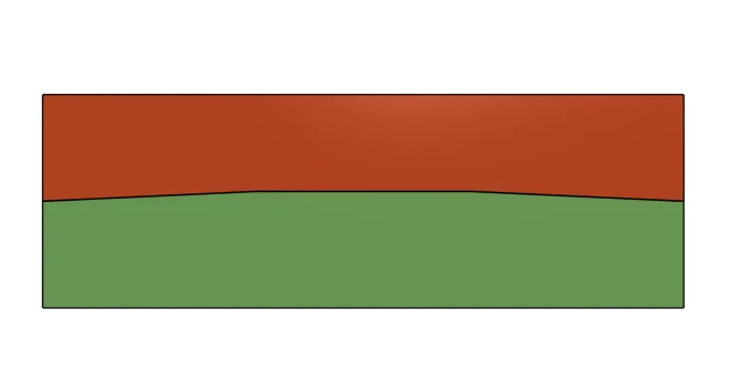
Next, move back to an alternating pattern and lap the two concave plates against each other:
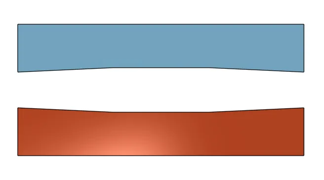
This results in two fairly flat plates. At this point, only the Green plates needs to be brought to the same level of flatness as the other two.
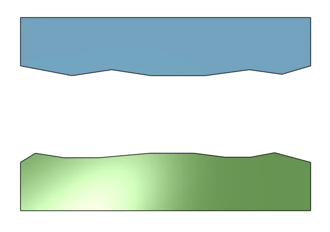
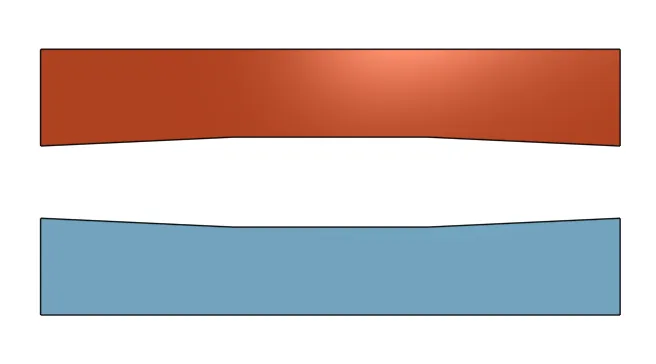
Step 6
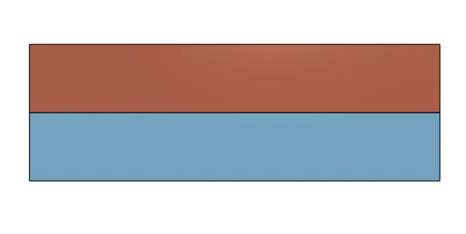
Finally, the single convex plate is lapped against the Blue control plate:
And the result is three plates that are in agreement with each other!
It’s also worth noting that, although this yields great precision “from nothing”, Joseph Whitworth later improved upon the technique by utilizing engineer’s blue and hand scraping, as mentioned previously. Engineer’s blue alone would be an instrumental improvement over using no indicator - with the blue, it’s easy to see which areas have, and haven’t been, scraped.
Let me know if you’ve tried this yourself or have any comments about how I can improve the instruction. Most of what I know about the original Three Plates Method came from this PDF.
Note: ericweinhoffer.com is a participant in the Amazon Services LLC Associates Program, an affiliate advertising program designed to provide a means for sites to earn advertising fees by advertising and linking to amazon.com.